


The transition from 2D sketching to 3D parametric modeling is one of the steepest learning curves in modern engineering education. For many undergraduates, the initial excitement of creating a part quickly turns into frustration when those parts refuse to “mate” correctly in a complex assembly. This “Assembly Crisis” isn’t just about software proficiency; it is about a fundamental shift in how we approach design intent and technical documentation.
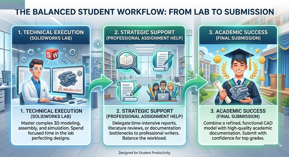
Navigating this transition requires more than just knowing which buttons to click. It demands a strategy for managing heavy academic workloads alongside precise technical execution. When students find themselves overwhelmed by the sheer volume of reports, literature reviews, and design logs required for their degree, seeking support from a professional assignment writer service can be a practical way to maintain high academic standards while focusing on mastering the core software skills. By delegating the heavy lifting of theoretical documentation, students can spend more time in the lab or the design studio, where the actual “building” and innovation happen.
The Evolution of the “Assembly Crisis”
In the current academic landscape, the bar for student projects has been raised significantly. It is no longer enough to simply model a static object. Professors now look for fully functional assemblies, motion studies, and stress analyses. This increased complexity has led to what many call the “Assembly Crisis,” where students find their computer screens filled with red and yellow warning icons as soon as they attempt to join two components together.
The struggle is often a mix of technical software hurdles and the mental fatigue of being a modern student. Engineering and technical degrees are notorious for their “crunch periods”—weeks where multiple high-stakes projects collide. During these times, the mental bandwidth required to debug a complex mate error in SolidWorks is often exhausted by the need to write 3,000-word ethics essays or study for thermodynamics exams.
Comparison: Common Student Errors vs. Professional Best Practices
To move from a struggling student to a proficient user, one must adopt the habits of industry professionals. The table below highlights the key differences in approach that can make or break a 3D project.
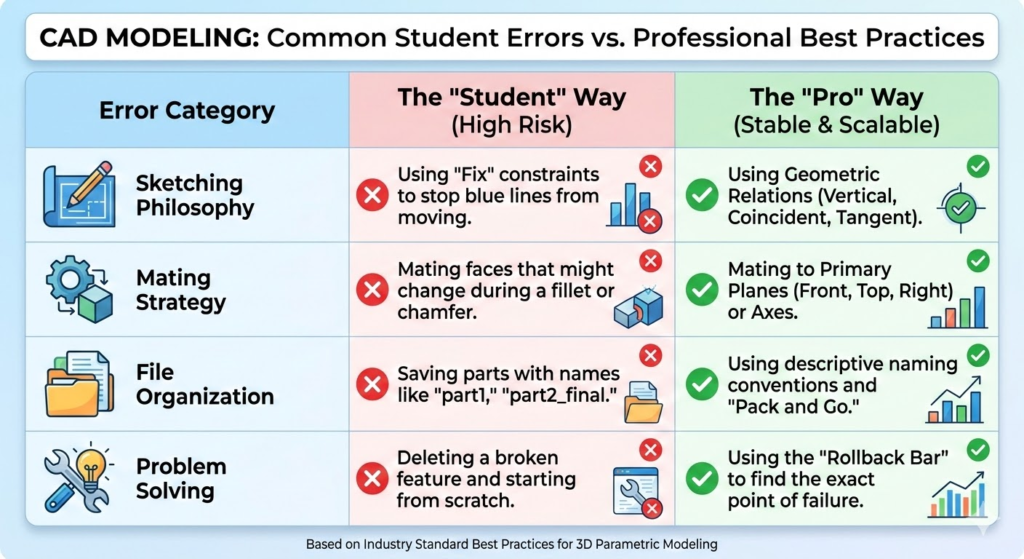
| Error Category | The “Student” Way (High Risk) | The “Pro” Way (Stable & Scalable) |
| Sketching Philosophy | Using “Fix” constraints to stop blue lines from moving. | Using Geometric Relations (Vertical, Coincident, Tangent). |
| Mating Strategy | Mating faces that might change during a fillet or chamfer. | Mating to Primary Planes (Front, Top, Right) or Axes. |
| File Organization | Saving parts with names like “part1,” “part2_final.” | Using descriptive naming conventions and “Pack and Go.” |
| Problem Solving | Deleting a broken feature and starting from scratch. | Using the “Rollback Bar” to find the exact point of failure. |
The Technical Wall: Why SolidWorks Feels Difficult
SolidWorks is a parametric modeler. This means it is driven by rules. Every dimension you enter and every relation you click is a “law” that the software must follow. The “Assembly Crisis” occurs when students inadvertently create laws that contradict one another.
For example, if you tell the software that Part A must be 50mm from Part B, but also that Part A must be centered on a hole that is only 40mm away, the software “breaks.” Undergraduates often spend hours chasing these errors without realizing that the problem started three steps ago in a simple sketch.
When you are stuck in a loop of conflicting constraints and the deadline is approaching at midnight, the pressure can be paralyzing. It’s often during these high-pressure moments that students realize they need a second pair of eyes to audit their work. This is why many engineering majors utilize specialized SolidWorks assignment help from Myassignmenthelp to debug their feature trees and understand exactly where their design intent went wrong. Getting a professional critique of your assembly structure isn’t just about finishing the task; it’s about seeing how an experienced engineer would organize those same components to ensure the model remains “robust” even if dimensions change later.
Mastering Design Intent
“Design Intent” is the secret language of CAD professionals. It refers to how your model behaves when it is modified. A well-designed model is “smart”—if you change the diameter of a rod, the hole it sits in should update automatically. If your model doesn’t do this, you haven’t finished the assignment; you’ve just made a digital sculpture.
To fix the struggle with design intent, undergraduates should focus on these three pillars:
- The Origin is Your Friend: Always start your first sketch on the Origin. This gives you a fixed point in space that will never move.
- Symmetry: Use the “Mirror” tool whenever possible. Not only does it save time, but it also ensures that your assembly remains balanced.
- Renaming the Feature Tree: Don’t leave your features named “Boss-Extrude1.” Rename them to “Main Body” or “Mounting Tab.” This makes debugging significantly faster when things go wrong.
The Global Student Experience: Balancing Theory and Practice
Whether you are studying in the UK, the US, Australia, or Canada, the pressures of an undergraduate degree are universal. The “Global Tone” of education today is one of high-speed delivery. Students are expected to be masters of software, excellent technical writers, and proficient researchers all at once.
This multidisciplinary demand is where many students stumble. You might be a brilliant designer, but if your technical report is poorly written, your grade will suffer. Conversely, you might be a great writer who simply cannot get their SolidWorks mates to stop “over-defining.” The key to success is identifying your bottlenecks and finding resources to clear them.
Why Documentation Matters Just as Much as the Model
In a real engineering firm, the 3D model is only half the job. The other half is the documentation—the “Why” behind the “What.” Professors mirror this requirement by asking for extensive project reports. This documentation must explain:
- Material selection and why it was chosen for the specific load.
- The safety factor of the design.
- How the assembly will be manufactured (Injection molding, 3D printing, CNC?).
For many students, the transition from the “visual” work of SolidWorks to the “analytical” work of a 15-page report is where the burnout happens. Using professional academic resources allows you to focus on the technical simulation while ensuring the accompanying essay or report meets the high linguistic and structural standards required by top-tier universities.
Troubleshooting the “Broken” Assembly
If you open your project and see a sea of red, don’t panic. Follow this professional troubleshooting workflow:
- The “Yellow” Warning: This usually means a mate is missing a reference (perhaps you deleted a face it was attached to). Simply “Edit Feature” and pick a new face.
- The “Red” Error: This means two mates are fighting. Suppress all your mates and turn them back on one by one. The moment the red error reappears, you’ve found the culprit.
- The “Interference” Check: Use the Evaluate tab to run an Interference Detection. This will show you where parts are physically overlapping—a major red flag in any assignment.
The Path to First-Page Academic Success
Ranking at the top of your class—and eventually ranking in your career—requires a holistic approach. It is about more than just surviving the “Assembly Crisis.” It is about building a toolkit of resources that you can rely on when things get tough.
By understanding the mechanics of SolidWorks, focusing on design intent, and knowing when to reach out for professional academic support, you can turn a stressful assignment into a portfolio-worthy masterpiece. The modern student doesn’t have to struggle in isolation; the tools and expertise are available to ensure you cross the finish line with both a working model and a top-tier grade.
Frequently Asked Questions (FAQ)
Q: Why does my SolidWorks assembly lag so much?
A: This usually happens because the software is trying to calculate too much detail. Go to “Tools > Options > Document Properties > Image Quality” and turn the slider down. Also, avoid adding threads or complex logos until the very end of the project.
Q: What is the best way to learn SolidWorks for free?
A: Start with the built-in tutorials inside the software (Help > SolidWorks Tutorials). They are often better than random YouTube videos because they follow the correct parametric logic.
Q: How do I handle a project where I have to write a long report alongside the CAD model?
A: Break the tasks apart. Spend your mornings on the CAD model when your brain is fresh for logic, and use your evenings for drafting the report. If the writing becomes a bottleneck, don’t hesitate to use an assignment writer service to help structure your theoretical sections.
Q: My mates are all correct, but my part still moves. Why?
A: You likely have a “degree of freedom” still open. Use the “Fully Define Component” tool or check if the part has a small (-) minus sign next to its name in the feature tree.
Q: Is SolidWorks used in the real world, or just in school?
A: It is one of the most widely used CAD programs in the world, especially in the medical device, automotive, and consumer product industries. Mastering it now is a direct investment in your future salary.Final Tip: Always use the “Pack and Go” feature when submitting your work. This ensures that your professor receives all the part files and not just an empty assembly shell!